Alignment
1. Introduction
The "Align"-page can be accessed by selecting the
corresponding tab in the main window
or by pressing the "Ctrl+2"-key while the pointer is in the main window.
This window is the area where to align the desktop beamline
with the X-ray beam. The principles of alignment are described in chapter
"Principles of Operation" of the
Introduction.
Within this window you can:
- find the X-ray beam from scratch
- reoptimize the X-ray beam
- obtain a 3-D beam profile
- determine appropriate slit apertures
- manually move motors for positioning the dtb
The "Align"-window features several work areas:
- a menu bar (see 2.1)
- a status area in the upper quarter of the window (see 2.2)
- a parameter input area for different tasks in the second quarter of the window (see 2.3)
- a drawing area where reading readings of both ionization chambers are plotted in the lower half of the window (see 2.4)
2. Work Areas
The dtb features a variety of functions that have to do with moving the alignment motors. Availabel functions are:
| Function | Description |
|---|---|
| Find beam | Find beam from scratch |
| Optimize beam | Optimize beam assuming that the dtb already sees some beam. |
| Profile beam | Establish a 3-D beam profile |
| Shape beam | Determine appropriate beam apertures |
| Adjust ADC | Readjust the ADC offsets |
| Manual operation | Move hor. and ver. translations and rotations individually |
2.1 Align Menu
The Align-menu pops up if the "Align" button in the menu bar has been pressed or if "Alt+a" is pressed while the pointer is in the main window.
| Menu | Menu Choice | Description |
|---|---|---|
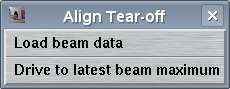
| Load beam data | Open beam file and display contents in plot area |
| Drive to latest beam maximum | Drives all positional motors to the maximum the latest refined positions |
2.1.1 Load beam data
This window allows to open and display files that have been created previously and that contain beam profiles, beam scans or beam history. These files are stored by program mar5dtb in directory $MARLOGDIR/beam and usually 99 version of either file type dtb.scan.N, dtb.profile.N and dtb.time.N are stored. The number N is configurable (see below). Instead of manually loading single files it is usually more convenient to scroll through previous beam file using the arrow buttons in the drawing area (see below).
2.1.2 Drive to latest maximum
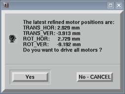
This window allows to drive directly all translational and rotational motors to the most recent refined positions. A motor position will be treated as refined if it has gone either through the "Find beam" or "Optimize beam" procedure. This option is very useful if for some reason the motors have been moved manually, or if for instance beam optimization has been started without X-rays.
The refined positions will even be written to a data file and read by program mar5dtb at program startup, so the values are available even after program restart.
2.2 Status Area
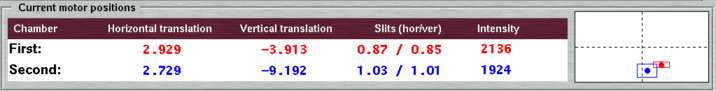
The "Status Area" shows the current positions of the motors that have to do with ionization chamber 1 (TRANS_VER, TRANS_HOR, SLIT_1_VER, SLIT_1_HOR) and with ionization chamber 2 (ROT_VER, ROT_HOR, SLIT_2_VER, SLIT_2_HOR), respectively. For both chamber, the current chamber reading is displayed as well. Note, that all components of chamber 1 are colored red and all components of chamber 2 are colored blue. This rule also applies to the intensity plots in the drawing area.
The plot in the right corner of this area is a representation of the motor positions relative to their possible range of translation. It is assumed that all motors have previously been initialized properly. In the plot given above, the red dot stands for the motor positions TRANS_HOR and TRANS_VER (1. chamber) and the blue one for the motors ROT_HOR and ROT_VER (2. chamber). In both cases, the horizontal motor is almost in the center of its range of movement and the vertical motor somewhat closer to the lower end.
The use of this plot is the following: for optimization of the beam it is important that the actual X-ray beam is not too close to one of the limits of the movements. Otherwise, the instrument cannot completely drive over the beam and cannot properly determine the maximum. Even if the movements of the motors are all relatively ample, you may want to stay away from the edges of the movements and ideally end up relatively close to the centers of movements. The graphical representation of the motor positions is much more intuitive than looking at the actual numbers in mm, since this would require you to know where the minimum and where the maximum of the motors are, and this is really too much hazzle.
Depending on the current operation, there will be some rectangles drawn around the dots, in particular during the "Find beam" and "Optimize beam" procedure. These rectangles mark the way the motors are going to move during the procedure. The sizes of the rectangles vary depending on the optional settings for the corresponding tasks (see below).
2.3 Input Parameter Area
The "Input Parameter Area" allows for setting some parameters that affect the behaviour of the individual tasks. Depending on the choosen task, the layout of this area will change. Only the most relevant parameters may be changed, e.g. speed parameters or slit apertures, etc.. See below for more details.
2.4 Plot Area
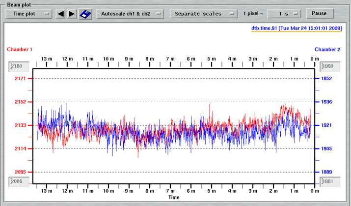
The "Plot Area" displays the readings of ionization chambers 1 (red) and 2 (blue). There are 3 different plot types:
-
Time plot:
Usually, the desktop beamline controller sends status information at a rate of 1/second. The time plot follows the readings over the course of time, i.e. you will see the history of the intensity over some period of time. Many people know this utility from visits to synchrotron sites. On home X-ray sources, you may see instabilities of the generator. If the resulting plot shows a smooth decrease it may also indicate the need of readjusting the ADC offset at some stage. Due to changes in ambiental conditions ADC offsets may drift.By default, 1 pixel on the screen corresponds to 1 second. For the width of the "Align"-window this corresponds to 14 minutes. By selecting other time units (e.g. 1 pixel = 10 s) you extend the period of time to be displayed. At the largest scale this will be many days.
-
Scan plot:
The desktop beamline can digitize ionization chamber readings while moving any motor. The time resolution is 154 microsec per digitization! Hence, the mapping of intensity reading to motor position is extremely precise. This utility therefore allows for very accurate determination of X-ray beam maxima and is heavily used during all tasks of automatic beam alignment. During a scan incoming data are automatically scaled and displayed. On the x-axis you will find the positions of the moving motor. See also chapters Find Beam, Optimize Beam, Profile Beam and Shape Beam for more details -
Beam profile:
The program allows for establishing a beam profile and display this profile. See chapter Profile Beam for more details.
At the top of the drawing area, there is a menu bar where you can select which type of plot you want to look at. For certain plot types, there are additional input options.
Table 2: The "Plot Area" options
| Symbol | Plot type | Description |
|---|---|---|

| All | Choice of type of plottype: time, scan or beam plot |

| All | Load previous or next plot (either time, scan or profile). Note, that the name of currently loaded file is displayed in the upper right corner of the plot area. The latest file is written on white background and underlined in orange. Otherwise, the background will be grey. |

| All | Save current plot to file. The o/p-file will always be called beamplot.xwd and will go to the working directory. Existing beamplot.xwd files will be overwritten without warning. The file format is "XWD" (X Windows system window dump file). There are utilities for converting this format into many other image formats (png, jpg), the most useful and popular being the ones from the ImageMagick suite available for all Unix flavours, in particular program convert. |

| Time & Scan | Choice of automatic adjustment of scales. By default (autoscale), the ymin and ymax-values of both red and blue curves are adjusted automatically. Thus, the plot always makes use of the entire drawing range in y. You may provide your own min. and max. values by disabling autoscaling for either chamber 1 and chamber 2 readings. |

| Time & Scan | Choices for scaling plots for chambers 1 and 2 onto eachother. Usually, the readings in chamber 1 are larger than in chamber 2. Due to automatic adjustment of y-scales, the user may not see the difference. When scaling chamber 2 onto chamber 1 readings, ymin and ymax-values of chamber 1 readings are used to scale chamber 2 readings. When using separate scales, the blue curve is scaled according to the y-axis scales on the right hand side. |
| | Time | Each pixel on the screen corresponds to a defined period of time. By choosing smaller or larger conversion numbers you may shorten or extend the total amount of time to be displayed. Note, that the starting time of the program sets the start of all menu choices. Only if the program stays up for some time, you will see some beam history for the 1 pixel = 30 min choice. |

| Time | Disable further updates of plot in TIME mode. Toggles with button Continue. Note, that the program keeps updating the beam history internally while pausing the display update. |

| Profile | Zoom factor for displaying the beam profile. With large zoom factors, the beam profile may not fit in the window, but scroll bars will allow to inspect all areas. |

| Profile | In the corresponding text fields on the right hand side you may manually enter min. and max. values for distributing grey scales in the beam profile plot. All pixels > max. are drawn in black and all pixels < min. are drawn in white. All pixels inbetween get some shades of grey. |
3. Alignment Tasks
3.1 Find Beam
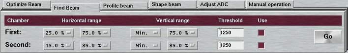
The "Find Beam"-tool can be accessed by selecting the corresponding choice in the "menubar" or by pressing the "Alt+f"-key while the pointer is in the "Align"-window.
The purpose of the "Find Beam"-procedure is to find the X-ray beam from scratch, i.e. without knowing at all where the beam is going to pass through the 2 pairs of slits. The typical situation is that there is no significant intensity reading in chamber 1 and that the alignment motors will have to move some way to see the beam. For this procedure to work we have to assume that there is only 1 primary beam coming out of the monochromator.
BEWARE:
If there are multiple beams as produced by mirror systems and if the unwanted beams (i.e. polychromatic) are not cut out before entering the collimator of the dtb, this procedure has little chances to work
The variable parameters for this procedure are the following:
Table 3: The input parameters for "Find Beam"
| Parameter | Description |
|---|---|
| Horizontal range | Starting and ending position of search box in horizontal direction.
The choices are given in percent of the possible movements. The default is configurable (see chapter Configuration File in section Input). The current choice is visualized by the boxes drawn around the red or blue dots in the plot area of the status area. |
| Vertical range | Starting and ending position of search box in vertical direction.
The choices are given in percent of the possible movements. The default is configurable (see chapter Configuration File in section Input). The current choice is visualized by the boxes drawn around the red or blue dots in the plot area of the status area. |
| Threshold | When finding an intensity above threshold, the program assumes that the X-ray beam has been found. This value MUST be larger than the ADC offset. A value of twice the ADC offset should be regarded as a suitable condition. |
| Use | Choice of searching the beam in chamber 1 or chamber 2 only. |
The sequence of tasks within the procedure is as follows. Note, that the procedure may be interrupted any time by pressing the "Stop"-button.
- Open slits of current chamber to 4.0 mm (wide open).
- Drive horizontal motor to left edge of search box.
- Make a horizontal scan to right edge of search box. Check wether there is some intensity above the given threshold. If there is, continue with next step. If there is not sufficient intensity, move 4.0 mm up (or down) and scan horizontally along next line. Repeat this step until finding a significant peak or until entire search box is covered.
- If previous step succeeded, drive to beam maximum.
- Close horizontal slit until intensity drops below given threshold.
- Make a horizontal scan covering the entire peak found previously with the reduced horizontal slit size and drive to found maximum.
- Repeat the previous 2 steps until hor. slit size is ≤ 0.8 mm.
- Do the same thing (i.e. previous 3 steps) for the vertical slit.
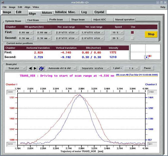
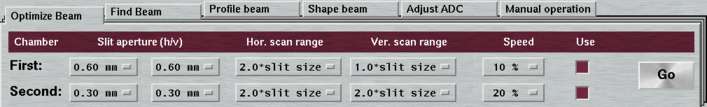
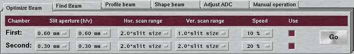
3.2 Optimize Beam
The "Optimize beam"-tool can be accessed by selecting the corresponding choice in the "menubar" or by pressing the "Alt+o"-key while the pointer is in the "Align"-window.
The purpose of the "Optimize Beam"-procedure is to reoptimize the X-ray beam with small slit apertures. It is important if not essential that the X-ray beam is already seen in the corresponding chamber, since the movements implemented within this procedure are all relatively small. The procedure is not going to work if the actual beam is not within a fraction of a millimeter from the current motor positions.
NOTE:
Due to the weight of the mounted detectors the statics of the desktop beamline varies as soon as the distance translation or the 2-theta stage are moved. This can produce a considerable drop of X-ray intensity in the ionization chambers. A reoptimization is therefore strongly recommded after moving any of these motors.
The data collection menu offers the choice for doing an optimization before starting the data set. It is generally suggested to activate this choice.
The parameters for beam optimization depend on the nature of the X-ray beam, i.e. the type of optics used. As a rule of thumb, for optimizing the first chamber, the slits should be opened to an aperture that corresponds approximately to the beam size at this point. Typical values for Osmic mirrors are 0.7 to 0.6 mm. After refining the first chamber, the slits in the first chamber will be closed down, typically to 0.3 to 0.4 mm and the second chamber should be refined also with small slit apertures. The variable parameters for this procedure are the following:
Table 4: The input parameters for "Optimize Beam"
| Parameter | Description |
|---|---|
| Slit aperture (h/v) | Hor. and ver. slit aperture used for reoptimizing this chamber.
The choices are given in mm. The default is configurable (see chapter Configuration File in section Input). |
| Horizontal scan range | Range of movement of horizontal motor about current position.
The choices are given as function of current slit aperture. A scan range should be choosen such that the scan covers the entire beam and drops down to the baseline at both sides of the peak. Typical values are 2 to 3 * slit size. The current choice is visualized by the boxes drawn around the red or blue dots in the plot area of the status area. |
| Vertical scan range | Range of movement of vertical motor about current position.
The choices are given as function of current slit aperture. A scan range should be choosen such that the scan covers the entire beam and drops down to the baseline at both sides of the peak. Typical values are 2 to 3 * slit size. The current choice is visualized by the boxes drawn around the red or blue dots in the plot area of the status area. Note, that the vertical translation (TRANS_VER) is relatively slow compared to all other translations since here the dtb has to work heavily against gravity! |
| Speed | The speeds for doing the scans are not very critical. Slow speeds may make the result a bit more precise. Best to leave at defaults. The choices are provided as percentage of the maximum motor speed. Note, that the vertical translation (TRANS_VER) will always work with 100% speed, regardless of the choice made here. This is because that motor is quite slow anyway. |
| Use | Choice of optimizing the beam in chamber 1 or chamber 2 only. |
The sequence of tasks within the procedure is as follows. Note, that the procedure may be interrupted any time by pressing the "Stop"-button.
- Open slits of current chamber to the given choice (see input parameters). by the horizontal and vertical scan range as provided by the input parameters and is visualized in the status area (see above).
- Make a horizontal scan to right edge of search box.
- Go back to refined peak maximum in horizontal plane.
- Drive vertical motor to lower edge of search box.
- Make a vertical scan to upper edge of search box.
- Go back to refined peak maximum in vertical plane.
- Move the slits back to their original apertures.
Note, that from version 2.2 on the vertical movements will be interrupted by default, as soon as the instrument moves out of the beam. This implies, that the provided vertical scan range may not entirely be covered! This behaviour can significantly reduce the optimization time. It can be turned off by a keyword in the configuration file (see chapter Configuration File in section Input).
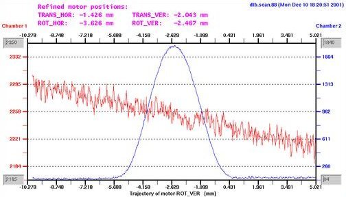
The next figure shows a typical result of an optimization of chamber 2. The actual scan of motor ROT_VER is drawn as blue line. Note, that the red line that marks the readings of chamber 1 shows a slight slope. Ideally the readings in chamber 1 should not be affected when using the rotational motors. In practice, the rotations are not completely discoupled from the translations!
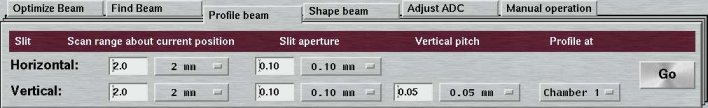
3.3 Profile Beam
The "Profile beam"-tool can be accessed by selecting the corresponding choice in the "menubar" or by pressing the "Alt+p"-key while the pointer is in the "Align"-window.
The purpose of the "Profile Beam"-procedure is to get a feeling for the characteristics of the X-ray beam. The procedure eventually comes up with an image of the beam that corresponds to what you see on a fluorescent screen or on an X-ray eye (e.g. marcam®) but with more detail. For this procedure to work the first ionization chamber must have been well optimized previously.
NOTE:
The procedure can take quite a while to finish. It consists of a long series of horizontal scans, typically 20 to 40 and some vertical translations inbetween. If you interrupt the procedure, you should use the "Drive to latest maximum"" option to return to the refined positions.
The variable parameters for this procedure are the following:
Table 5: The input parameters for "Profile Beam"
| Parameter | Description |
|---|---|
| Scan range about current position | Range of horizontal and vertical movements.
The range should be big enough to entirely cover the beam, at least 1 mm. The larger the vertical range, the longer the beam profiling takes. |
| Slit aperture | Hor. and ver. slit aperture used in chamber 1. The aperture should be rather small, e.g. 0.10 mm. |
| Vertical pitch | Advance of vertical motors after scanning 1 horizontal line.
Should be smaller or equal to vertical slit aperture. Note that the vertical pitch actually determines the time the procedure takes, since the vertical movements are much slower than the horizontal ones. |
| Profile at | The entire procedure can be done for either chamber 1 or chamber 2. |
The sequence of tasks within the procedure is as follows. Note, that the procedure may be interrupted any time by pressing the "Stop"-button.
- Close slits of chamber 1 or 2 to "slit aperture" (see input parameters).
- Drive horizontal translation to lower left edge of profile box. The profile box is defined by the horizontal and vertical scan range as provided by the input parameters and is visualized in the status area (see above).
- Make a horizontal scan to right edge of profile box.
- Drive vertical translation up by "vertical pitch" (see input parameters)
- Drive horizontal translation back to left edge in order to avoid backlash problems.
- Repeat previous 3 steps until entire profile box is covered.
- Go back to original position for horizontal and vertical translations.
- Move the slits back to their original apertures.
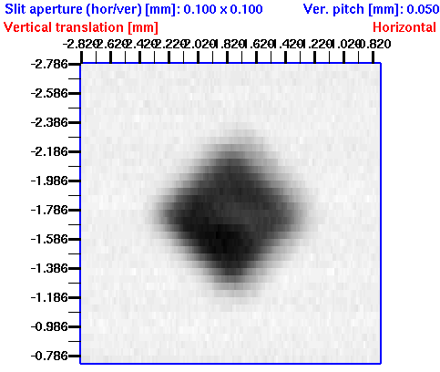
A typical beam profile from an Osmic mirror would look like this:
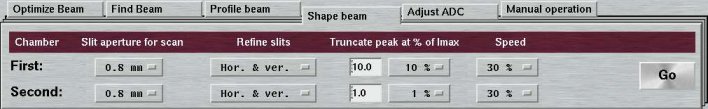
3.4 Shape Beam
The "Shape beam"-tool can be accessed by selecting the corresponding choice in the "menubar" or by pressing the "Alt+s"-key while the pointer is in the "Align"-window.
The purpose of the "Shape Beam"-procedure is to get a feeling for the size of the X-ray beam as it passes the collimator. For procedures "Find Beam", "Optimize Beam" and "Profile Beam" the translation or rotation motors have to be moved. For "Shape Beam", only the slits move! The procedure finishes with a suggestion of slit apertures. It is very useful to know how your beam hits the crystal in order to optimize your experiment. Regardless of the size of the crystal, you should run this procedure every time you are changing something on the X-ray source (mirror alignment, filament change, changes in power and bias settings of the generator, etc.). For this procedure to work both chambers must have been well optimized previously.
NOTE:
For this procedure to work it is essential that all slits are properly initialized, i.e. that the slit apertures as shown by the software corresponds to the dial readings on the hardware.
Usually, the slits in chamber 1 should be used to give the beam its desired shape. The slits of chamber 2 should not truncate the beam any more. The used slit apertures for the experiment depend on the size of the crystal. If the crystal is very small, you may want to cut out some part of the beam which is not going to hit the crystal and only contributes to background.
The variable parameters for this procedure are the following:
Table 6: The input parameters for "Shape Beam"
| Parameter | Description |
|---|---|
| Slit aperture for scan | Aperture for slit that stands still during scan. The aperture should be big enough to cover all or most part of the beam, e.g. 0.8 mm. |
| Refine slits | Choice of refining or horizontal or vertical slit or both or none for this chamber. |
| Truncate peak at % of Imax | Decision constant were to truncate the beam. Technically, the plots resulting from slit scans are integrated and the percentage given refers to the integrals and not just to the maximum. For chamber 1 you will usually want to cutoff some part of the beam, typically 5 to 10 %. For chamber 2, usually a 1 % cutoff is doing a good job. |
| Speed | The speeds for doing the scans are not very critical. Slow speeds may make the result a bit more precise. Best to leave at defaults. The choices are provided as percentage of the maximum motor speed. |
The sequence of tasks within the procedure is as follows. Note, that the procedure may be interrupted any time by pressing the "Stop"-button. Note also, that if you choose to refine slits in chamer 2 only, slits in chamber 1 won't be moved at all but stay where they are.
- Open vertical slit of chamber 1 to "slit aperture" (see input parameters).
- Open horizontal slit to 3.0 mm (see input parameters).
- Make a horizontal slit scan from 3.0 to 0.0 mm.
- Repeat previous 3 steps for the other slit.
- Analyze curves and drive slits to their optimized positions.
- Repeat previous steps for slits in chamber 2.
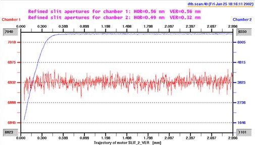
The next figure shows a typical result of an optimization of chamber 2. The
The next figure shows a typical slit scan of slits in chamber 2 from an Osmic mirror. The actual slit scan is marked with the blue line. The red line is the intensity in chamber 1 and stays on one level during this particular operation.
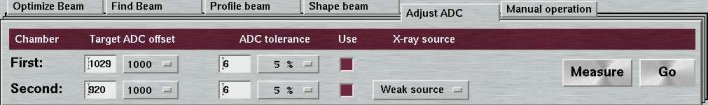
3.5 Adjust ADC
The "Adjust ADC"-tool can be accessed by selecting the corresponding choice in the "menubar" or by pressing the "Alt+a"-key while the pointer is in the "Align"-window.
The purpose of the "Adjust ADC"-procedure is to set the baseline of the analogue-to-digital converters (ADC). The ADC's are highly sensitive and show fluctuations, in particular with temperature and humidity variations of the environment. In general, the baseline should be set to a value large enough for the ADC readings to stay in the positive range. The dtb controller implements a procedure to set the ADC baseline to a certain target value. The controller also features an electronical gain selector which offers the possibility to switch between strong X-ray sources (synchrotrons) and weak X-ray sources (rotating anodes, sealed tubes). The difference in sensitivity is a factor of approx. 250.
When pressing the "Measure"-button, the current ADC offset is actually measured. For this purpose, the slits in the first chamber are closed and the horizontal translation motor moves by approx. 3 mm. The ADC-values without X-rays will then be determined for both chambers. Since in "Weak source" mode the fluctuations can be in the order of +/- 500 counts, for very weak sources like Mo- or Ag-sources it may become important to accurately determine the current ADC offset values before attempting a beam optimization.
NOTE:
This procedure should best be executed with no X-rays at all entering the collimator.
The variable parameters for this procedure are the following:
Table 7: The input parameters for "Adjust ADC"
| Parameter | Description |
|---|---|
| Target ADC offset | Target value for baseline. Suggested values are: 1000 for weak X-ray sources and 20 for strong X-ray sources. |
| ADC tolerance | This value determines the speed of convergence of the adjustment
procedure.
Suitable choices are 5 % to 10 % of the target offset. |
| Use | Choice of adjusting ADC offsets in chamber 1 or chamber 2. |
| X-ray source | Gain selector for strong sources (synchrotrons) or weak sources
(all others). Note that when operating at gain settings of strong sources, the fluctuations of ADC readings also become very small. |
3.6 Manual Operations
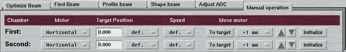
The "Manual Operations"-tool can be accessed by selecting the corresponding choice in the "menubar" or by pressing the "Alt+m"-key while the pointer is in the "Align"-window.
This window layout offers the possibility to move motors TRANS_HOR, TRANS_VER, ROT_HOR and ROT_VER individually. Under normal conditions this won't be necessary, but there are certain cases where it can be useful, e.g. if the "Find Beam"-procedure fails because there is more than one primary beam entering the collimator. In that case, you will have to decide yourself which beam is the one you want to look at. You should manually drive the translational motors close to that beam and only use the "Optimize Beam"-procedure for fine-tuning. Once the desired beam passes through the first pair of slits, the "Find Beam"-procedure can be used to catch the beam in the second chamber.
NOTE:
Violating common GUI-programming rules, in the input parameter area the choice +1 mm (and related) below the "Move motor" section will directly produce the action. Usually, option menues are not tied to an immediate action, but for the sake of saving space here we don't stick to this convention.
The variable parameters for this procedure are the following:
Table 8: The input parameters for "Manual Operation"
| Parameter | Description |
|---|---|
| Motor | Choice of driving either hor. and ver. motor. When selected, the "Target Position" field will automatically be updated with the current position of the motor. |
| Target position | Textfield and menu with prominent choices for desired position. |
| Speed | Choices are provided as percentage of the maximum motor speed. |
| Move motor | By pressing the "To target" button the motor will move to the
position given in the "Target position" field. By selecting one of the menu choices, the corresponding motor will immediately start driving by a certain amount of mm. |
| Initialize | Initialize the corresponding motor at one of the end switches. |